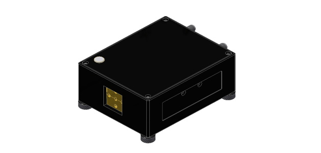
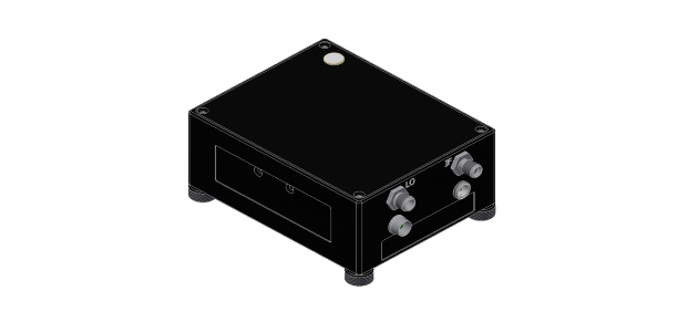
コンパクトアップ・ダウンコンバーター (CC)
導波管ミキサー
概要
Virginia Diodes (VDI) 社は周波数アップおよびダウンコンバージョン用のコンパクトコンバーター(CC)を提供しています。これらのコンバーターは使いやすく、広帯域変調ミリ波信号の高性能アップおよびダウンコンバージョンに最適です。
CCは導波管の全帯域をカバーし、WR28(22.5-40 GHz)から WR10(75-110 GHz)まで利用可能です。
CCUの両側波帯の性質によりアップコンバージョンプロセス中に2つの側波帯(上側波帯と下側波帯)が生成されます。特定のアプリケーションでは1つの側波帯を除去するためにフィルターが好ましい場合があります。
Compact Converter Configurations
Compact Up-Converter (CCU)
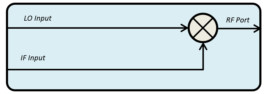
Compact Down-Converter (CCD)
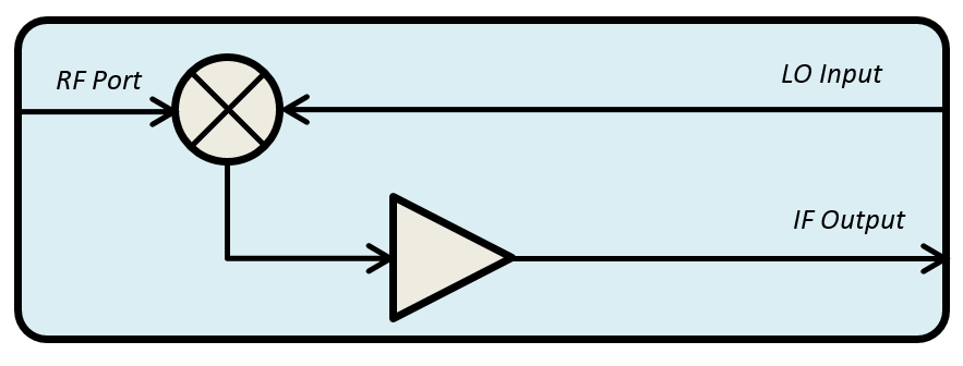
ダウンロード
Compact Converter Product Manual
DOWNLOAD
仕様
WR28 to WR12
| Product Specifications for Compact Up-Converters (CCU) |
||||
| WR28CCU | WR19CCU | WR15CCU | WR12CCU | |
| LO Input Frequency (GHz) |
22.5-40 | 20-30 | 25-37.5 | 30-45 |
| PLO, LO Input Power (dBm, typical / damage)* | 0 / 10 | 0-3 / 6 | 0-6 / 9 | 0-6 / 9 |
| IF Input Frequency (GHz) | 0.01-8.5 | 0.01-6 | 0.01-9 | 0.01-12 |
| PIF, IF Input Power (dBm, ~P1dB / ~P0.1dB) | 8 / -5 | -4 / -14 | PLO - 10dB / PLO - 20dB | |
| PIF, IF Input Power (dBm, damage) | 10 | 6 | 0 | |
| RF Output Frequency (GHz) | 22.5-40 | 40-60 | 50-75 | 60-90 |
| RF Output Flange | WR-28 UG-599/U-M | WR-19 UG-599/U-M | WR-15 UG-387/U-M | WR-12 UG-387/U-M |
| LO Input Connector | 2.92mm(f) | 2.92mm(f) | 2.92mm(f) | 2.4mm(f) |
| IF Input Connector | 2.92mm(f) | |||
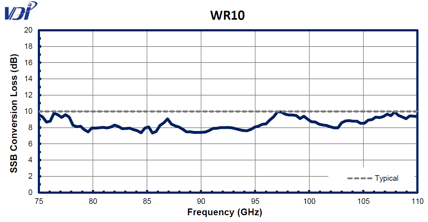
| Conversion Loss (typ., dB)†† | 10 | 10 | 10 | 10 |
| Operating Temperature (Typical / Recommended) |
25°C / 20-30°C | |||
| Typical Dimensions (in., without footplate) | 3.75 x 3.00 x 1.50 | |||
| Product Specifications for Compact Down-Converters (CCD) |
||||
| WR28CCD | WR19CCD | WR15CCD | WR12CCD | |
| LO Input Frequency (GHz) |
22.5-40 | 20-30 | 25-37.5 | 30-45 |
| PLO, LO Input Power (dBm, typical / damage) | 0 / 10 | 0-3 / 6 | 0-6 / 9 | 0-6 / 9 |
| IF Output Frequency (GHz) | 0.0001-8.5 | 0.0001-6 | 0.0001-9 | 0.0001-12 |
| PRF, RF Input Power (dBm, ~P1dB / ~P0.1dB) | 8 / -5 | -4 / -14 | PLO - 10dB / PLO - 20dB | |
| PRF, RF Input Power (dBm, damage) | 10 | 6 | 0 | |
| IF Amplifier Gain (dB)† | ~12 | |||
| RF Input Frequency (GHz) | 22.5-40 | 40-60 | 50-75 | 60-90 |
| RF Input Flange | WR-28 UG-599/U-M | WR-19 UG-599/U-M | WR-15 UG-387/U-M | WR-12 UG-387/U-M |
| LO Input Connector | 2.92mm(f) | 2.92mm(f) | 2.92mm(f) | 2.4mm(f) |
| IF Output Connector | 2.92mm(f) | |||
| Conversion Loss (typ., dB)†† | 10 | 10 | 10 | 10 |
| Operating Temperature (Typical / Recommended) |
25°C / 20-30°C | |||
| Typical Dimensions (in., without footplate) | 3.75 x 3.00 x 1.50 | |||
*LO Input Power for optimal conversion loss varies with LO input frequency.
†CCD modules include an IF amplifier with ~12dB gain.
††Conversion Loss is defined as the intrinsic mixer conversion loss without any external amplifiers.
General Notes:
•VDI CCs include a single volt power supply.
•The required LO power for optimal performance varies across the frequency band. Performance specifications assume optimal RF and LO power coupled into the mixer; performance may be reduced near band edges.
•Conversion Loss performance is specified at ~1 GHz IF. Conversion loss increases as a function of IF, at a rate of ~1.5dB/10GHz, up to the specified Maximum IF Frequency. Performance is typical with reduced performance at band edges.
•RF Filters can be used to eliminate one sideband of the CCR RF output. Contact VDI for more information.
•RF amplifiers can be used to increase the CCU RF output power. Contact VDI for more information.
•Where available, an input isolator will smooth the required LO input power vs. frequency.
Performance Plots
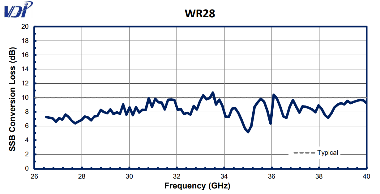
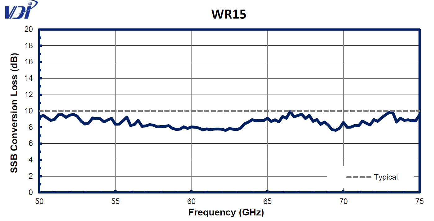
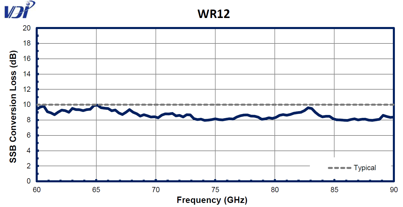
WR10 and Higher Frequency
| Product Specifications for Compact Up-Converters (CCU) |
||||
| WR10CCU | WR6.5CCU* | WR6.5CCU-M12* | WR5.1CCU | |
| LO Input Frequency (GHz) |
37.5-55 | 18.3-28.3 | 9.2-14.2 | 23.3-36.7 |
| PLO, LO Input Power (dBm, typical / damage)* | 6-12 / 15** | 0-6 / 12 | 0-6 / 12 | 0-6 / 12 |
| IF Input Frequency (GHz) | 0.01-15 | 0.01-17 | 0.01-17 | 0.01-22 |
| PIF, IF Input Power (dBm, ~P1dB / ~P0.1dB) | PLO - 10dB / PLO - 20dB | -1 / -11 | ||
| PIF, IF Input Power (dBm, damage) | 0 | 6 | ||
| RF Output Frequency (GHz) | 75-110 | 110-170 | 110-170 | 140-220 |
| RF Output Flange | WR-10 UG-387/U-M | WR-6.5 UG-387/U-M | WR-6.5 UG-387/U-M | WR-10 UG-387/U-M |
| LO Input Connector | 1.85mm(f) | 2.92mm(f) | 2.92mm(f) | 2.92mm(f) |
| IF Input Connector | 2.92mm(f) | |||
| Conversion Loss (typ., dB)†† | 10 | 12 | 12 | 12 |
| Operating Temperature (Typical / Recommended) |
25°C / 20-30°C | |||
| Typical Dimensions (in., without footplate) | 3.75 x 3.00 x 1.50 | |||
| Product Specifications for Compact Down-Converters (CCD) |
||||
| WR10CCD | WR6.5CCD | WR6.5CCD-M12 | WR5.1CCD | |
| LO Input Frequency (GHz) |
37.5-55 | 18.3-28.3 | 9.2-14.2 | 23.3-36.7 |
| PLO, LO Input Power (dBm, typical / damage)* | 6-12 / 15** | 0-6 / 12 | 0-6 / 12 | 0-6 / 12 |
| IF Output Frequency (GHz) | 0.0001-15 | 0.0001-17 | 0.0001-17 | 0.0001-22 |
| PRF, RF Input Power (dBm, ~P1dB / ~P0.1dB) | PLO - 10dB / PLO - 20dB | -1 / -11 | ||
| PRF, RF Input Power (dBm, damage) | 0 | 6 | ||
| IF Amplifier Gain (dB)† | ~12 | |||
| RF Input Frequency (GHz) | 75-110 | 110-170 | 110-170 | 140-220 |
| RF Input Flange | WR-10 UG-387/U-M | WR-6.5 UG-387/U-M | WR-6.5 UG-387/U-M | WR-5.1 UG-387/U-M |
| LO Input Connector | 1.85mm(f) | 2.92mm(f) | 2.92mm(f) | 2.92mm(f) |
| IF Output Connector | 2.92mm(f) | |||
| Conversion Loss (typ., dB)†† | 10 | 12 | 12 | 12 |
| Operating Temperature (Typical / Recommended) |
25°C / 20-30°C | |||
| Typical Dimensions (in., without footplate) | 3.75 x 3.00 x 1.50 | |||
*The WR6.5CCU and WR6.5CCU-M12 has the option to integrate a WR6.5 (110-170 GHz) Power Amplifier inside the module. The WR6.5AMP has a gain of ~20dB typical and ~P1dB of +10dBm typical. Part numbers for this option would be WR6.5CCU-HP and WR6.5CCU-M12-HP respectively. Contact VDI for more information.
**LO Input Power for optimal conversion loss varies with LO input frequency.
†CCD modules include an IF amplifier with ~12dB gain.
††Conversion Loss is defined as the intrinsic mixer conversion loss without any external amplifiers.
General Notes:
•VDI CCs include a single volt power supply.
•The required LO power for optimal performance varies across the frequency band. Performance specifications assume optimal RF and LO power coupled into the mixer; performance may be reduced near band edges.
•Conversion Loss performance is specified at ~1 GHz IF. Conversion loss increases as a function of IF, at a rate of ~1.5dB/10GHz, up to the specified Maximum IF Frequency. Performance is typical with reduced performance at band edges.
•RF Filters can be used to eliminate one sideband of the CCR RF output. Contact VDI for more information.
•RF amplifiers can be used to increase the CCU RF output power. Contact VDI for more information.
•Where available, an input isolator will smooth the required LO input power vs. frequency.
Performance Plots
